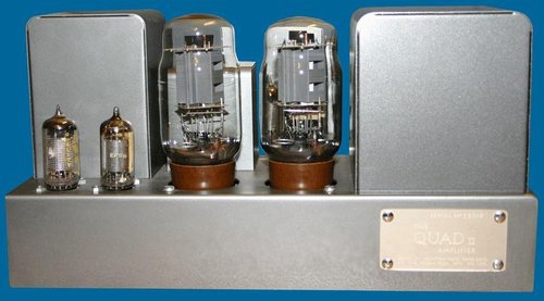
MyAv網站上有人提問:
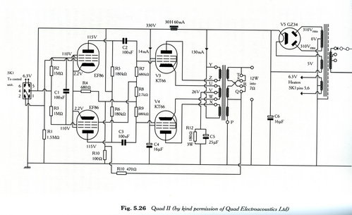
QUAD 2輸出變壓器屏級阻抗Zp-p是多少K歐姆?
陰級阻抗Zk-k是多少歐姆?
這是很有意思的問題。
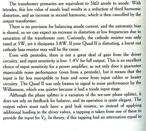
按照Morgan Jones書上貼文,Zp-p=3k歐姆,但是沒提到陰極阻抗Zk-k是多少歐姆。
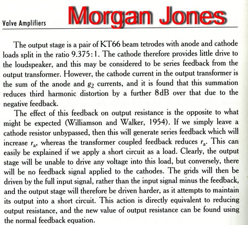
他的說法 Anode and cathode loads split in the ratio 9.375:1
loads 一字有些費解。
解說法-1:
如 load 單純是指 impedance 則:
Zp-p/Zk-k= 9.375 ----------------(1)
Zp-p + Zk-k= 3k歐姆-------------(2)
解上列(1) (2)代數式
得到 Zk-k= 3k/(1+9.375)= 289歐姆
解說法2:
如 load 是指 功率P負載 則: P=I*I*Z
Zp-p/Zk-k= 65*65*3000/(65+7)*(65+7)*Zk-k= 9.375
解出 Zk-k=261歐姆
解說法3:
如 load 是指 電壓輸出 E 則:
Ep-p/Ek-k=9.375=初級/次級的圈數比
Zp-p/Zk-k= 初級/次級的圈數比的平方=9.375*9.375=87.9
解出:Zk-k= 3000/(1+87.9)= 34歐姆
按照 :
keith網站
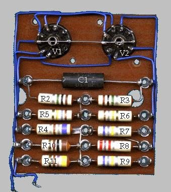
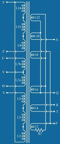
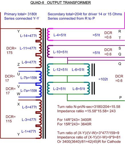
The winding scheme on the left appears to be accurate for the QUAD II output transformer — spec 1003A — and has been determined from my own dissections and from information generously supplied by others The first winding {closest to the core} L1 and all other odd numbered sections forming the primary are about 477 turns of 34 SWG {0.2mm} enamelled copper wire in 3 layers of about 159 turns — Between each layer are 2 layers of 0.05mm oiled paper — The tertiary windings L7a and L7b are each a single layer of 159 turns of 34SWG giving the the 1/9 cathode feedback Even numbered winding sections forming the secondary are each single layers of about 51 turns of 22 SWG {0.65mm} separated from the adjacent odd numbered windings by 2 layers of 0.16mm oiled paper on each side — The outside L14 is wound with a few layers of 0.16mm paper to finish R? is a small ~0.36Ω wire wound resistor as seen in picture below — presumably to prevent instability by dampening the Q of L2 which has the lowest resistance — Stability with feedback is helped by the fact that one third of the output winding for the 8Ω setting and one half for the 15Ω setting are outside the negative feedback loop so a short circuit or high capacitance on the output cannot completely shunt the feedback Majestic Transformer Co. in the UK make a replacement core that just fits in the original can in the correct orientation to the mains transformer — It has a low frequency response about an octave better than the original and does not require R? — The overall distortion is also much better compared to 5 original OPTs in the same amplifiers and with different valves Although the winding resistances are unequal (Y–Z 50% higher than X–Y) the turns ratios should be balanced — The approximate resistances and ratios of an unloaded output transformer normalised to 100V rms at 100Hz across X-Y are: Primary V4 — 115Ω to 120Ω — X—Y = 100V Primary V3 — 170Ω to 180Ω — Y—Z = 100V Cathode V4— 16.8Ω to 16.9Ω — U—V = 11V Cathode V3 — 16.5Ω to 16.6Ω — V—W = 11V Output — 0.55Ω to 0.61Ω — P—Q = 7.15V Output — 0.55Ω to 0.61Ω — Q—S = 3.58V 如果簡單拿 圈數比等於電壓比,則 100V/11V=9.09 阻抗比=圈數比的平方,則 Zp-p/Zk-k= 9.09*9.09=83 初級電壓總和=(100+11)*2=222 V 次級電壓總和=(7.15+3.58+3.58 =14.3 V 圈數比等於電壓比 =222/14.3=15.5 阻抗比=圈數比的平方=15.5*15.5= 241 則當次級 接上 15毆姆 時,反映到初級的阻抗是: (Zpp+Zk-k)=241*15=3615 毆姆 因此 Zk-k= 83 毆姆,Zp-p=3615-83=3532毆姆 再次拿實際測到的圈數計算, 為容易判讀起見,重新整理畫成下圖表: | |
 |
依照圈數比計算結果,列在上圖:
即是
1.
OPT OPT 初級、次級圈數比= 15.6 或
初級阻抗 3400(3640) 比 次級阻抗 14(15) 歐姆
2.
屏極阻抗、陰極阻抗比為 81 或
屏極阻抗、陰極阻抗 3358 (3595) 比 42(45) 歐姆
比較合乎 Morgan Jones 解說法 3
沒有留言:
張貼留言